Sep
28
Evolving Wire Specifications to Improve RF & Microwave Cable Performance
Developing the best possible helical wrap, braid, and center conductor products require an understanding of the role each plays in the assembled cable. Each component serves its function and therefore has characteristics that are most important to the success of the final cable. A common issue that can arise is the unwritten rules that must be met, especially with helical wrap wires. The solution for this breaks down into two parts, which are valuable to know for RF Cable manufacturers because it will help expedite the improvement of these wires' performance.
First, reverse engineering, both good and bad samples, to identify the characteristic that likely needs control for the cable's success is an excellent place to start.
After this, providing samples that represent changes that should be made to improve the performance of the overall system will be instrumental. If the samples are successful, then the data is used to write specifications to capture this critical detail.
Over time, once one problem has been settled, other issues are sometimes identified, and the exercise must be repeated with changes made to a new process parameter. Recently, the marketplace has begun to see a push for improvements in helical wrap wires that will allow cables to increase in bandwidth and overall length. There are two categories these generally fall into.
The first would be improving Fast Fourier Transformation (FFT) limits for better Voltage Standing Wave Ratio (VSWR) performance. The second would be changing mechanical properties, so the wire can better handle the wrapping process and avoid increases in resistance after undergoing any type of motion.

What is FFT?
The Fourier Transform is a mathematical operation that changes the domain (x-axis) of a signal from time to frequency. The latter is particularly useful for decomposing a signal consisting of multiple pure frequencies. You can probably already tell that the FFT is a rather complicated algorithm. The Fourier Transform is a method for representing an irregular signal — such as the voltage fluctuations in the wire between an output device and an input device — as a combination of pure frequencies. Fast Fourier Transform is one of the most important algorithms in the information sciences and essential for ensuring performance in precision RF Cable wire manufacturing.
It is critical because when producing data cables, any irregularities such as variations of diameter, eccentricity, and capacitance pose a risk for data transmission in the final cable product. Understanding how the precision metals used to make RF Cable play into the entire production process is very beneficial in producing a cable that will perform as intended. Ulbrich Specialty Wire Products dives deeper into this in their on demand webinar hosted on Microwaves&RF.
The production of RF Cables begins with the production of the different items that make up the cable, such as the various wires that are needed to make it.
Introducing VSWR
You might be asking, wait, "what is VSWR?" VSWR is the ratio of the maximum voltage to the minimum voltage in standing wave pattern along the length of a transmission line structure and is used to measure differences in impedance. It is very similar to Structural Return Loss. These terms describe the uniformity of a cable's impedance along its length related to reflected energy. The difference between VSWR and SRL is essentially a difference in how reflected energy is measured. For the purposes of this article, we will focus on VSWR at the material level for high-performance cable manufacturing.
As the demands for higher performance cables permeate information sciences and technologies, so does the demand for the precision wire which are free of irregularities that can disrupt the signal transfer across long lengths of cable. In a perfect system, 100% of the RF power would transmit through a lossless line, uninterrupted. By reducing VSWR, cable manufacturers can reduce reflections and lower the impedance between components. This achievement starts with engineered materials, wire, manufactured to best-in-class standards using cutting edge technology, which minimizes imperfections that result in signal loss.
Managing VSWR levels by dialing in FFT during the manufacturing of RF cable raw materials is essential to achieving predictable, high performance RF Cable.
Improving Fast Fourier Transformation (FFT) Limits for Better VSWR Performance
The best RF wire manufacturers have systems in place for measuring Fast Fourier Transformations (FFTs) on dimensional data during production which allows for the ability to make improvements in VSWR performance, for wrap wire applications. This technological capability enables the ability to measure width and thickness FFTs for repeating periods down to 0.1" or up to 1000" in length.
By imposing limits over the live FFT graph, a production operator can be informed if there is a machine issue causing a repeating pattern that will show up in a VSWR plot. Varying limit levels can be applied to FFT magnitudes, depending upon the cable design and required VSWR limits. Occasionally the limit level chosen at the beginning of development appears adequate because no issues arise in the first cables assembled. As production increases, the magnitude of the FFT spikes can vary inside the initial limit from batch to batch. When this happens, VSWR plots from these batches of wire can be compared to FFT plots to determine the need for a tighter FFT limit.
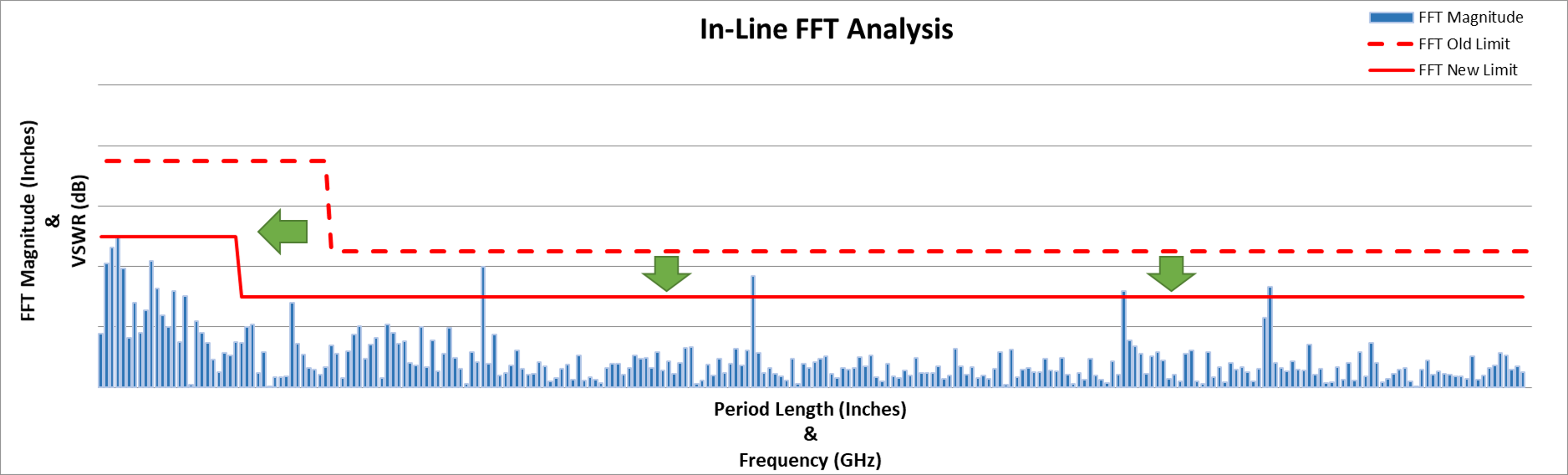
This is an example of the FFT used during production. The period length on the x-axis correlates with frequency on VSWR plots and the FFT magnitude on the y-axis correlates with decibel level on VSWR plots. It also shows how FFT limits might need to be tightened to compensate for changes in bandwidth or new VSWR requirements such as lower decibel limits.
Such iterations could require manufacturing process adjustments, which could potentially have unforeseen consequences on other properties in the wire, and consequently in the cable. Collaborative technical dialogue between the wire and cable engineers provides the best opportunity to optimize all wire & cable production processes to achieve the best possible characteristics in the cable. If an adjustment to the wire process is required, it is prudent to produce a small sample spool of wire with the proposed changes; which the cable maker can test under engineering supervision. Once the desired results are confirmed, the revised wire specification and the process moves into mass production.
How Precise Mechanical Property Control Aids Micro-Bending of Helical Wrap Wire
Changing mechanical properties can also improve the performance of helical wrap wire. This has less to do with VSWR performance and more to do with how the wire itself handles the wrapping process. The thickness of these wires tends to be on the order of 0.002" (0.050mm) and is being wrapped around diameters around the order of 0.020" (0.50mm). Because of the small orders of magnitude involved here, the wrapping of a shield wire around a dielectric could be categorized as a micro-bending process. Micro-bending refers to thin foils being formed around tight radii. The behaviors observed during micro-bending don't follow classic formability laws associated with sheet metals. In this realm, the ratio of grains per unit thickness of foil begins to dictate the behavior of the material during forming. For these reasons, the process of helically wrapping the shielding or wrap wire around the dielectric qualifies as micro-bending. To achieve the unique microstructure (micro-temper) optimal for the cable, the wire maker needs to develop an appropriate thermal treatment process. The etching of copper grains can sometimes be more of an art than a science, so it is not a reliable means to write a specification. Fortunately, each of these unique microstructures has a unique set of mechanical properties that can be used to efficiently ensure the heat-treated (annealed) wire has the appropriate micro-temper.
Understanding Micro-Tempers for Cable Applications
Many times, specifications determine the temper of a wire by the elongation of the wire. Some cable manufacturers find softer wire better handles their wrapping process, but that elongation alone will not guarantee their success from batch to batch. Cable manufacturers should realize that softness is not the only thing to consider, and there are other mechanical properties that better predict how the material will respond when it is wrapped. To help show the difference in mechanical properties of different micro-tempers, and how they impact the wire during wrapping, please see the illustration below, showing the stress-strain curve from a tensile test of pure copper in the "Soft" condition and the resulting properties in the table to its right. The elongation is determined by how far the material stretches before it breaks. The reason this may not accurately describe the wire's behavior during wrapping is that the wire is not being pushed to complete failure. Tensile strength describes the stress the material must undergo to reach its maximum elongation at failure, so this also fails to describe the material's behavior under wrapping tension. The yield strength, however, occurs at about half of the applied force of the tensile strength and 1% elongation. When the yield strength is crossed during a tensile test, it means that the wire has shifted from elastic to plastic deformation.

This plots a typical stress-strain curve from pure copper in its soft condition.
Elastic deformation means that enough stress has been applied to the wire to make it slightly elongate but that it will return to its original length if the stress is relieved. Plastic deformation means that enough stress has been applied for the wire to elongate past the point at which it can return to its original length if the stress is relieved. Let's imagine a case where the stress applied exceeds the yield strength (stress of 20,000psi) and the wire plastically deforms. If we find where the stress-strain curve of the "Soft" micro-temper reaches 20,000psi, and look down at the x-axis we see elongation of 10%, so we know 20,000 psi is applied the wire will elongate from 10" in length to 11" and will stay at 11" in length when let go. For cable makers struggling to have helical wrap wire that is soft enough based only upon the elongation measurement, an "Extra Soft" micro-temper could help. By reducing the yield strength of the wire, the wire will require less tension during wrapping to undergo the same amount of deformation. This does come at a slight cost to the tensile and elongation, but that should not be of concern if the wire is not pushed to the point of failure.

Here is shown stress-strain curves comparing pure copper in soft and extra-soft tempers.
A "Tough" micro-temper has a much higher yield strength than is typically found in annealed copper. While the overall tensile strength is slightly higher as well, the nearly 2x normal yield strength value is what is truly unique. This means that a stress that would break a standard annealed copper wire won't even permanently deform wires annealed to this micro-temper. Again, there is always a give and take when changing mechanical properties and the "Tough" wire usually has around 15% elongation. But we know that high strength copper alloys used in some cable applications only have around 8% elongation, and that renders them soft enough to survive their handling in the machine. While it doesn't have quite the yield strength of a "Soft" high strength copper alloy, one advantage of the "Tough" wire is that there is no conductivity loss since it is still a pure copper alloy. When comparing stress-strain curves as well as properties, you can see that it falls right between the traditional "Hard" and "Soft" conditions.
The "Tough" micro-temper could be ideal for applications where increased tension helps with cable performance yet traditional copper tempers cannot hold up under these tensions.

This set of plots compares the hard, tough, soft, and extra-soft tempers’ stress-strain curves.
Work Collaboratively with a Wire Partner to Unlock Your Cable's True Potential
High-performance cable producers would be well served to partner with a technically competent wire supplier who can help enable the best possible performance in their cables. The wire producer needs to be able to measure and control a variety of subtle variables. These variables, once understood, can be written into specifications that result in performance gains in the assembled cable. When the wire and cable makers work collaboratively, these characteristics are captured so that manufacturing time and purchasing funds are not wasted on defective cables. The wire producer can become an integral part of the cable development team. There is no one size fits all solution for developing cable wires. Some problems that arise when moving to full-scale production can only be solved by a joint effort between the wire and cable engineers.


